DFRobot IO Expansion Shield v5.0
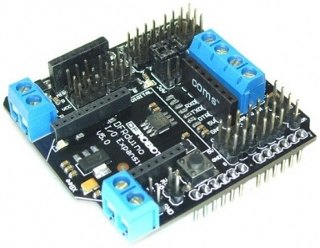
Photo credits: unknown
Shield URL: IO Expansion Shield v5.0
Tags: input, output, communications, xbee, bluetooth, sd, storage
Maker: DFRobot
Supports:
- RS485
- Xbee (Xbee pro)
- Bluetooth
- APC220
- SD card read/write
Open Source: Unknown
License: Unknown
Source: Unknown
|
|
I do not yet have verified pin usage data for this shield.
Note:
This shield must use many more pins than are indicated here, but I can't find a schematic anywhere or any useful technical docs on the DFRobot site.
The screw terminals (assuming that the three jumpers are set to '485') marked 'A' and 'B' go directly to the IC 'A' and 'B' pins (6 & 7 respectively).
Screw terminal "VCC" goes to the IC VCC pin (8), and also to Arduino 5V.
Screw terminal "GND" goes to the IC GND pin (5), and also to Arduino GND.
The chip's DI (Data Input?) pin (4) is connected to Arduino D1/TX.
The chip's RO (Data Output?) pin (1) is connected to the Arduino D0/RX, with a resistor pull-up to +5V.
The chip's DE (output enable) pin (3) is connected via a resistor to Arduino D3: active high. The DE pin is also connected to the chip's RE bar (receiver enable) pin (2) and therefore controlled by the Arduino's Digital pin 3 too: active low.
|